GearPump4_CL
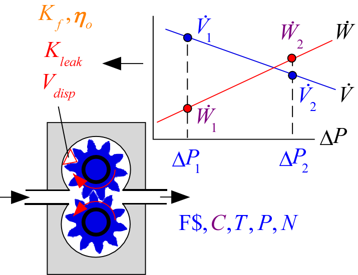
The procedure GearPump3_CL is a simple model of a gear pump that requires the displacement of the pump as well as three empirical parameters: K_leak, K_f, and eta_o. The procedure GearPump4_CL estimates these parameters based on performance data from a specific gear pump in order to provide a generally useful model of that gear pump that can be used to estimate performance over a range of speeds, fluids, and operating conditions. You must provide the procedure with the operating condition (fluid, state and pump speed) and then two data points along the pump curve: (V_dot_1, DELTAP_1) and (V_dot_2, DELTAP_2). Optionally you can also provide power at the two data points (W_dot_1 and W_dot_2). The procedure returns the displacement and leakage coefficient. If powers are provided then it also returns the friction coefficient and overall efficiency.
Call GearPump4_CL(F$, C, T, P, N, V_dot_1, DELTAP_1, W_dot_1, V_dot_2, DELTAP_2, W_dot_2: V_disp, K_leak, K_f, eta_o)
Inputs:
F$: fluid string identifier
C: concentration (%) {applicable when F$ is a brine. Otherwise set C=0.}
T: temperature (K, C, F, or R)
P: pressure (bar, atm, Pa, kPa, MPa)
N: rotational speed (1/s)
V_dot_1: volumetric flow rate for 1st data point (m^3/s or in^3/s)
DELTAP_1: pressure rise for 1st data point (bar, atm, Pa, kPa, or MPa)
W_dot_1: optional power for 1st data point (W, kW, or Btu/hr) - set to negative number if not provided
V_dot_2: volumetric flow rate for 2nd data point (m^3/s or in^3/s)
DELTAP_2: pressure rise for 2nd data point (bar, atm, Pa, kPa, or MPa)
W_dot_2: optional power for 2nd data point (W, kW, or Btu/hr) - set to negative number if not provided
Outputs:
V_disp: displacement of pump per cycle (in^3 or m^3)
K_leak: leakage constant (-)
K_f: friction constant (W-s/m^3 or Btu/in^3); only provided if powers are given, otherwise set to -1
eta_o: overall efficiency of pump (-); only provided if powers are given, otherwise set to -1
Example:
The curve below is for an Oberdorfer N2000 pump.
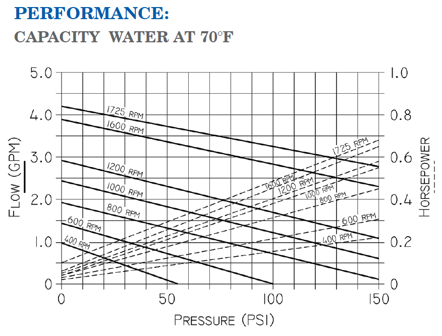
Two data points taken from the performance curve at 1200 rpm are:
V_dot_1 = 2.9 [gpm], DELTAP_1 = 0 [psi], W_dot_1 = 0.025 [hp]
V_dot_2 = 1.1 [gpm], DELTAP_2 = 150 [psi], W_dot_2 = 0.58 [hp]
$Load Component Library
$UnitSystem SI Mass C kPa J
$VarInfo V_disp Units = 'm^3'
$VarInfo K_f Units = 'W-s/m^3'
F$ = 'Water'
T = 20 [C]
P = 100 [kPa]
N = 1200 [1/min]*Convert(1/min,1/s)
V_dot_1 = 2.9 [gpm]*Convert(gpm,m^3/s)
DELTAP_1 = 0 [psi]*Convert(psi,kPa)
W_dot_1 = 0.025 [hp]*Convert(hp,W)
V_dot_2 = 1.1 [gpm]*Convert(gpm,m^3/s)
DELTAP_2 = 150 [psi]*Convert(psi,kPa)
W_dot_2 = 0.58 [hp]*Convert(hp,W)
CALL GearPump4_CL(F$, 0 [%], T, P, N, V_dot_1, DELTAP_1, W_dot_1, V_dot_2, DELTAP_2, W_dot_2: V_disp, K_leak, K_f, eta_o)
{Solution:
V_disp = 0.000009148 [m^3] {9.148 [cc]}
K_leak = 1.202e-8 [-]
K_f = 101900 [W-s/m^3]
eta_o = 0.4572 [-]
}
These parameters can now be used with GearPump3_CL to provide performance predictions under different operating conditions.
$Load Component Library
$UnitSystem SI Mass C kPa J
$VarInfo DELTAP Units='kPa'
$VarInfo W_dot Units = 'W'
F$ = 'Water'
T_in = 20 [C]
P_in = 100 [kPa]
N = 1600 [1/min]*Convert(1/min,1/s)
V_disp = 0.000009148 [m^3] {9.148 [cc]}
K_leak = 1.202e-8 [-]
K_f = 101900 [W-s/m^3]
eta_o = 0.4572 [-]
V_dot = 3.0 [gpm]*Convert(gpm,m^3/s)
m_dot = V_dot*Density(F$,T=T_in, P=P_in)
CALL GearPump3_CL(F$, 0 [%], T_in, P_in, N, V_disp, m_dot, K_leak, K_f, eta_o: DELTAP, W_dot, eta_p, eta_v)
{Solution:
DELTAP = 498 [kPa] {72.23 [psi]}
W_dot = 290.6 [W] {0.3897 [hp]}
eta_p = 0.3244
eta_v = 0.7759
}
See also: GearPump3_CL