GlobeValve_CL
This procedure provides a model of a globe valve. The resistance coefficient for the valve is obtained from the procedure K_GlobeValve in the Heat Transfer & Fluid Flow library which uses the correlation published in:
Flow of Fluids Through Valves, Fittings, and Pipe, Crane Valves North America, Technical Paper No. 410M. 1979
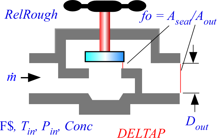
Call GlobeValve_CL(F$, T_in, P_in, Conc, m_dot, D_out, RelRough, fo: DELTAP)
Inputs:
F$: fluid string identifier
T_in: inlet temperature (K, C, F, or R)
P_in: inlet pressure (bar, atm, Pa, kPa, MPa)
Conc: concentration (%) {applicable when F$ is a brine. Otherwise this input is ignored.}
m_dot: mass flow rate (kg/s or lbm/s)
D_out: outlet diameter of valve (m or ft)
RelRough: roughness of valve normalized by diameter (-)
fo: ratio of the valve seat area to the outlet area (-). As valve is closed fo will approach 0.
Outputs:
DELTAP: pressure rise (bar, atm, Pa, kPa, or MPa)
Example:
$Load Component Library
$UnitSystem SI Mass C kPa J
$VarInfo DELTAP Units='kPa'
F$ = 'ATF'
T_in = 20 [C]
P_in = 200 [kPa]
m_dot = 0.02 [kg/s]
D_out = 0.005 [m]
RelRough = 0.001 [-]
fo = 0.2
CALL GlobeValve_CL(F$, T_in, P_in, 0 [%], m_dot, D_out, RelRough, fo: DELTAP)
{Solution:
DELTAP = 106.9 [kPa]
}