EnthalpyExchanger1_CL
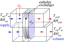
EnthalpyExchanger1_CL models a rotary enthalpy exchanger in which provides heat and mass (water) exchange between two air streams. The device is used to precondition ventilation air from outdoors before it is blown into a building space. The enthalpy exchanger matrix is assumed to be made of a corrugated material, such as aluminum, that has been coated with a desiccant material. Heat exchanger coefficients are found using the Triangular_channels function in the Heat Transfer Convection library. An example of this device is the enthalpy wheel manufactured by Carnes, in Verona, WI as documented in Freud (2003). However, the model should be appropriate for most enthalpy exchanger geometries. The model is based on the following assumptions:
1. Dynamic steady state operation
2. Uniform properties of the matrix and both air streams at each axial position over the regenerator.
3. Uniform inlet and outlet streams.
4. Negligible heat conduction and vapor diffusion in angular and axial directions.
5. Negligible entrainment of air from one period to the next.
6. Adiabatic operation.
7. Wheel rotation is sufficiently fast such that the performance is independent of angular speed. The speed corresponds to approximately 10-20 revolutions per minute for most enthalpy exchanger designs. See Freud, p. 44 for a criterion to evaluate the critical speed.
8. Lewis number is 1.
Following the recommendations in Freund, the supply air is preheated if condensation of exhaust air is expected. The implemented control strategy increases the supply air temperature in 2 C increments until condensation no longer occurs. The power required to preheat the supply air is provided in output Q_dot_ph
References:
Freund, S.W., "Simulation of Air-to-Air Energy Recovery Systems for HVAC Energy Conservation in an Animal Housing Facility", M.S. Thesis, Mechanical Engineering, Solar Energy Laboratory, University of Wisconsin - Madison, 2003., http://sel.me.wisc.edu/publications-theses.shtml
Inputs:
P: atmospheric pressure (Pa, kPa, bar, MPa,atm, psia)
A_fr: frontal area (m^2, ft^2)
L: width of exchanger (m,ft) in the flow direction
Porosity: porosity of regenerator packing (-)
D_h: hydraulic diameter of a the flow channels (m,ft)
Area\Vol: surface area per unit volume (1/m, 1/ft)
eta_fan: efficiency of the fan
T_oa: temperature of supply air from outdoors entering exchanger (C,K,F,R)
RH_oa: relative humidity of supply air from outdoors entering exchanger (-)
V_dot_oa: volumetric flow of supply air from outdoors (m^3/s, cfm)
T_ea: temperature of exhaust air from indoors entering exchanger (C,K, F, R)
RH_ea: relative humidity of exhaust air from indoor entering exchanger (-)
V_dot_ea: volumetric flow of exhaust air (m^3/s, cfm)
Outputs:
T_ph: temperature to which outdoor air is preheated to avoid condensation (C,K,F,R)
T_exit: temperature of air entering building (C,K,F,R)
RH_exit: relative humidity of air entering building (-)
Capacity: product of the mass flow rate, specific heat and temperature rise of supply air (W, kW, Btu/hr)
Power: required fan power (W)
Q_dot_ph: rate energy transfer from auxiliary source to prevent supply air to avoid condensation
epsilon: heat and mass transfer effectiveness of the enthalpy exchanger
R_c: capacitance rate ratio the two air flows
Example:
$Load Component Library
$UnitSystem SI C kPa kJ mass
P=Po# "atmospheric pressure"
A_f=0.539 [m^2] "frontal area of wheel"
L=0.203 [m] "depth of wheel in the flow direction"
Porosity=0.85 "porosity of the packing"
D_h=1.72 [mm]*convert(mm,m) "hydraulic diameter of the packing"
Area\Vol=255 [m^2]/(A_f*L) "area/volume of the packing"
eta_fan=0.6 "fan efficiency"
T[0]=-8 [C] "outdoor air (supply) temperature"
RH[0]=0.95 "relative humidity of supply air"
V_dot[0]=2.0 [m^3/s] "volumetric flow of supply air"
T[2]=24 [C] "temperature of exhaust air"
RH[2]=0.5 "relative humidity of exhaust air"
V_dot[2]=V_dot[0] "volumetric flow rate of exhaust air"
Call enthalpyexchanger1_cl(P,A_f,L,Porosity,D_h,Area\Vol,eta_fan,T[0],RH[0],V_dot[0],T[2],RH[2],V_dot[2]:T[1],T[3],RH[3], Capacity,Power,Q_dot_ph,epsilon,R_c)
omega[0]=humrat(AirH2O,T=T[0],P=P,R=RH[0]) "for plotting on psychrometric chart"
omega[1]=omega[0] "preheat air with no humidity change"
omega[2]=humrat(AirH2O,T=T[2],P=P,R=RH[2]) "humidity ratio of exhaust air"
omega[3]=humrat(AirH2O,T=T[3],P=P,R=RH[3]) "humidity ratio of supply air exiting enthalpy exchanger"
The results were used to produce the overlay on the psychrometric chart. Note that the inlet set (-8 C, 0.95 rh) was preheated to -6 C at constant humidity ratio to avoid condensation. The blue dotted line shows what would have happened without the preheating. The supply air exits the enthalpy exchanger at state 3.
