CoolingCoil1_CL
CoolingCoil1_CL models the performance of a heat exchanger designed to cool humid air. The model detects whether or not condensation occurs and calculates the heat transfer appropriately, following the method described in Mitchell and Braun, Heating, Ventilation, and Air Conditioning in Buildings, section 13.6, 2013. The theory behind this component is described in section SM 2.1 Heat Exchangers for Cooling Applications, which is an electronic supplement to the book. To summarize, the model first calculates the heat transfer rate and outlet temperatures assuming that the coil surface is dry using standard counterflow heat exchanger relations. Then, an enhanced heat/mass transfer coefficient is calculated assuming that the coil surface is wet. An analogy method is employed to determine an wet coil effectiveness based on the difference between the enthalpy of the inlet air and the enthalpy of saturated air at the water inlet temperature. The heat transfer rate, outlet air and water temperatures, and the rate of condensate removal are calculated. Mitchell and Braun demonstrate that the estimate of the heat transfer rate for a fully-wet coil serves as a good approximation for a partially wetted coil, and that assumption is employed in the model. If the condensate removal rate is greater than zero, then the heat transfer rate and outlet temperatures are as determined for the fully-wet coil. Otherwise the values for a dry coil are assumed.
Inputs:
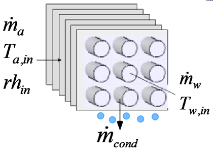
m_dot_a: mass flow rate of dry air (kg/s, lbm/hr)
T_a_in: inlet air temperature (C, F, K, R)
rh_in: inlet air relative humidity
P: atmospheric pressure (Pa, kPa, bar, MPa, atm, psia)
m_dot_w: mass flow rate of water (kg/s, lbm/hr)
T_w_in: inlet water temperature (C, F, K, R)
U_a: heat transfer coefficient on air side of coil (W/m^2-K, Btu/hr-ft^2-R)
A_a: heat transfer area on air side of coil (m^2, ft^2)
U_w: heat transfer coefficient on water side of coil (W/m^2-K, Btu/hr-ft^2-R)
A_w: heat transfer area on water side of coil (m^2, ft^2)
Outputs:
Q_dot: heat transfer rate (W, kW, Btu/hr)
T_a_out: outlet air temperature (C, F, K, R)
T_w_out: outlet water temperature (C, F, K, R)
m_dot_cond: condensate removal rate (kg/s, lbm/hr)
Example: (from Example 13.3 in Mitchell and Braun, Heating, Ventilation, and Air Conditioning in Buildings, 2013)
$Load Component Library
$UnitSystem Eng F psia mass
P = 14.7 [psia] "Pressure"
T_a_in = 80 [F] "Temperature"
T_wb_in = 64 [F] "Temperature"
rh_in=relhum(AirH2O,T=T_a_in,B=T_wb_in,P=P) "relative humidity"
m_dot_a = 21000 [lbm/hr] "Flow rate"
"Water side variables"
T_w_in = 42 [F] "Temperature"
m_dot_w= 30000 [lbm/hr] "Flow rate"
"Coil Parameters The symbol U_a is used for the overall surface effectiveness-heat transfer coefficient product"
U_a = 50 [Btu/hr-F-ft^2] "Unit conductance"
U_w = 1000 [Btu/hr-F-ft^2] "Unit conductance"
A_a = 360 [ft^2] "Area"
A_w = 18 [ft^2] "Area"
Call coolingcoil1_cl(m_dot_a, T_a_in, rh_in, P, m_dot_w, T_w_in, U_a, A_a, U_w, A_w : Q_dot, T_a_out, T_w_out, m_dot_cond)
{Solution:
m_dot_cond=16.58 [lb_m/hr]
Q_dot=165541 [Btu/hr]
T_a_out=52.17 [F]
T_w_out=47.5 [F]
}
See also: CoolingCoil2_CL