Condenser3_CL
Condenser3_CL determines the required heat transfer surface area for a finned circular tube geometry to condense a superheated refrigerant to a specified degree of subcooling. Thermal energy is rejected to an air stream. The heat transfer coefficients for the air and refrigerant are calculated using functions in the Heat Transfer Library based on geometry and flow information provided in the function call. The heat exchanger geometry name (HXg$) must be one of the finned circular types provided in the Compact Heat Exchanger library. See Condenser1_CL for an alternative call in which the heat transfer coefficients are provided.
This library file can be used in the design stage of the condenser by inputting the design inlet conditions to determine the required condenser size. Use Condenser4_CL to determine the refrigerant and air outlet states for given inlet conditions and condenser area.
Reference: Heat Transfer, Nellis and Klein, 2009, Cambridge University Press, section 8.5
Inputs:
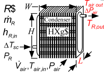
R$: name of the refrigerant
m_dot_R: refrigerant flow rate (kg/s, lbm/hr)
h_R_in: refrigerant inlet specific enthalpy (J/kg, kJ/kg, Btu/lbm)
DELTAT_sc: number of degrees of subcooling (C, K, F, R)
P_R: refrigerant pressure (Pa, kPa, bar, MPa, psia, atm)
V_dot: volumetric flow rate of air (m^3/s, cfm)
T_air_in: air inlet temperature (C, K, F, R)
P_air: air pressure (Pa, kPa, bar, MPa, psia, atm)
h_air: effective outside (air) heat transfer coefficient per unit refrigerant tube area (W/m^2-K, Btu/hr-ft^2-R)
HXg$: string identifier for a finned circular heat exchanger in the compact heat exchanger geometry
W: width of heat exchanger face parallel to tubes (m or ft)
H: height of heat exchanger face perpendicular to tubes (m or ft)
th_tb: tube thickness (m or ft); if set to a negative number then a reasonable value is assumed
N_circuits: number of parallel flow circuits for the refrigerant
Outputs:
L: length of heat exchanger in flow direction (m or ft)
A_R: required heat transfer area for the refrigerant (m^2, ft^2)
UA: overall heat transfer coefficient (W/K ,Btu/hr-R)
Q_dot: overall heat transfer rate (W, kW, Btu/hr)
h_R_out: outlet temperature of the refrigerant (J/kg, kJ/kg, Btu/lbm)
T_air_out: outlet temperature of the air (C, K, F, R)
DELTAP_air pressure loss of the air
f_sh: fraction of the condenser area that is in the superheat regime
f_sc: fraction of condenser area that is in the subcooled regime
Example:
$Load Component Library
$unitSystem SI C kPa kJ mass
$TabStops 0.2 4.5 in
$Varinfo A_R units=m^2
$Varinfo DELTAP_air units=kPa
$Varinfo L units=m
$VarInfo h_R_in units=kJ/kg
$VarInfo h_R_out units=kJ/kg
$VarInfo Q_dot units=kW
$VarInfo T_air_out units=C
$VarInfo UA units=W/K
R$='R134a' "refrigerant"
P_R=1 [MPa]*convert(MPa,kPa) "refrigerant pressure"
m_dot_R=0.0028 [kg/s] "refrigerant mass flow rate"
h_R_in=enthalpy(R$,T=95 [C], P=P_R) "specific enthalpy of entering refrigerant"
DELTAT_sc=4 [C] "subcooling"
V_dot_air=0.06 [m^3/s] "volumetric flow rate of air"
T_air_in=20 [C] "air inlet temperature"
P_air=1 [atm]*convert(atm,kPa) "air pressure"
HXg$='fc_tubes_s80-38T' "heat exchanger core name"
W=0.2 [m] "length of tubes"
H=0.2 [m] "height of flow channel"
th_tb = 0.9 [mm]*convert(mm,m) "tube wall thickness"
N_circuits=1 "number of parallel circuits"
Call condenser3_cl(R$, m_dot_R, h_R_in, DELTAT_sc, P_R, V_dot_air, T_air_in, P_air, HXg$, W, H, th_tb, N_circuits : L, A_R, UA, Q_dot, h_R_out, T_air_out, DELTAP_air, f_sh, f_sc)
{Solution:
A_R=0.1658 [m^2]
DELTAP_air=0.01472 [kPa]
f_sc=0.1932
f_sh=0.2681
h_R_out=101.4 [kJ/kg]
L=0.08554 [m]
T_air_out=28.81 [C]
UA=41.78 [W/K]
}