Evaporator4_CL
Evaporator4_CL determines the outlet air and refrigerant states for heat exchange between air and an evaporating refrigerant in a finned circular tube heat exchanger. The refrigerant may exit in a two-phase state or superheated. No consideration is provided for condensation or frost formation in this routine. It is necessary to provide the dimensions of the condenser and the type of surface, chosen from the list of compact heat exchangers. Heat transfer coefficients are calculated internally using the functions in the Heat Transfer Library. See Evaporator2_CL for a similar procedure that uses heat transfer coefficients supplied as parameters.
This library file can be used to calculate the outlet state of the of the evaporator with specified heat transfer area. Use Evaporator1_CL to determine the required area at design conditions.
Reference: Heat Transfer, Nellis and Klein, 2009, Cambridge University Press, section 8.5
Inputs:
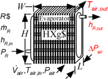
R$: name of the refrigerant
m_dot_R: refrigerant flow rate (kg/s, lbm/hr)
h_R_in: refrigerant inlet specific enthalpy (J/kg, kJ/kg, Btu/lbm)
P_R: refrigerant pressure (Pa, kPa, bar, MPa, psia, atm)
V_dot: volumetric flow rate of air (m^3/s, cfm)
T_air_in: air inlet temperature (C, K, F, R)
P_air: air pressure (Pa, kPa, bar, MPa, psia, atm)
HXg$: string identifier for a finned circular tube heat exchanger in the compact heat exchanger geometry
W: width of heat exchanger face parallel to tubes (m or ft)
H: height of heat exchanger face perpendicular to tubes (m or ft)
th_tb: tube thickness (m or ft); if set to a negative number then a reasonable value is assumed
N_circuits: number of parallel flow circuits for the refrigerant
Outputs:
Q_dot: overall heat transfer rate (W, kW, Btu/hr)
h_R_out specific enthalpy of exiting refrigerant (J/kg, kJ/kg, Btu/lbm)
T_air_out: outlet temperature of the air (C, K, F, R)
DELTAP_air pressure drop on air side
*A_air\A_R is the ratio of the product of the overall fin efficiency and total (finned and unfinned) area on the air side to the total surface area inside the refrigerant flow passages. For unfinned surfaces, A_air\A_R is the ratio of the outer surface to inner surface areas.
Example:
$Load Component Library
$unitSystem SI C kPa kJ mass
$TabStops 0.2 4.5 in
$Varinfo DELTAP_air units=kPa
$VarInfo h_cond_out units=kJ/kg
$VarInfo h_R_in units=kJ/kg
$VarInfo h_R_out units=kJ/kg
$VarInfo Q_dot units=kW
$VarInfo T_air_out units=C
$VarInfo T_R_out units=C
$VarInfo T_R_sat units=C
R$='R134a' "refrigerant"
m_dot_R=0.008 [kg/s] "refrigerant mass flow rate"
T_cond_out=38 [C] "condenser exit temperature"
P_cond=1 [MPa]*convert(MPa,kPa) "condenser pressure"
h_cond_out=enthalpy(R$,T=T_cond_out,P=P_cond) "specific enthalpy of refrigerant exiting condenser"
P_R=175 [kPa] "evaporator pressure"
T_R_sat=t_sat(R$,P=P_R) "evaporator saturation temperature"
h_R_in=h_cond_out "specific enthalpy of refrigerant entering evaporator"
x_R_in=quality(R$,h=h_R_in,P=P_R) "inlet quality"
T_air_in=5 [C] "air inlet temperature"
P_air=101.3 [kPa] "air inlet pressure"
V_dot_air=0.08 [m^3/s] "volumetric flow rate of air"
HXg$='fc_tubes_s80-38T'
th_tb = 0.9 [mm]*convert(mm,m) "tube wall thickness"
W=0.2 [m] "length of tubes"
H=0.26 [m] "height of flow channel"
L=0.1027 [m]
N_circuits=1 "number of parallel circuits"
Call evaporator4_cl(R$, m_dot_R, h_R_in, P_R, V_dot_air, T_air_in, P_air, HXg$, W, H, L, th_tb, N_circuits: Q_dot, h_R_out, T_air_out, DELTAP_air)
T_R_out=temperature(R$,h=h_R_out,P=P_R)
{Solution:
DELTAP_air=0.01798 [kPa]
h_R_out=225.9 [kJ/kg]
Q_dot=0.9647 [kW]
T_air_out=-4.47 [C]
T_R_out=-13.42 [C]
}