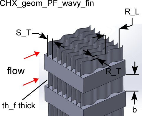
PF wavy-fin geometry

The procedure:
CHX_geom_pf_wavy_fin(TypeHX$: S_T, th_f, b, R_T, R_L, D_h, theta, beta, A_fin\A)
Provides the geometric data associated with a plate finned - wavy-fin type compact heat exchanger surface. These data are from Kays and London (1994).
Inputs:
The only input is the string identifying the geometry TypeHX$
11.44-3/8W: 'PF_wavy-fin_1144_38w'
11.5-3/8W: 'PF_wavy-fin_115_38w'
17.8-3/8W: 'PF_wavy-fin_178_38w'
Outputs:
S_T = transverse fin spacing (m or ft)
th_f = thickness of fin material (m or ft)
b = plate gap (m or ft)
R_T = tranverse ripple amplitude (m or ft)
R_L = longitudinal ripple amplitude (m or ft)
D_h = hydraulic diameter defined as 4 x minimum flow area x length/heat transfer area (m or ft)
theta = minimum flow area/frontal area for finned surface side only
beta = heat transfer area/volume (m^2/m^3 or ft^2/ft^3) for finned surface side only
A_fin\A = heat transfer area on fins/heat transfer area for finned surface side only
Example
$UnitSystem SI Mass J K Pa
$VarInfo beta units=1/m
$VarInfo R_L units=m
$VarInfo R_T units=m
$VarInfo S_T units=m
$VarInfo th_f units=m
TypeHX$= 'PF_wavy-fin_115_38W'
Call chx_geom_pf_wavy_fin(TypeHX$: S_T, th_f, b, R_T, R_L, D_h, theta, beta, A_fin\A)
{Solution:
S_T = 0.00221 [m]
th_f = 0.000254 [m]
b = 0.00925 [m]
R_T = 0.001981 [m]
R_L = 0.009525 [m]
D_h = 0.003023 [m]
theta = 0.860 [-]
beta = 1138 [m^2/m^3]
A_fin\A = 0.822}
Related procedures include: