Evaporator3_CL
Evaporator3_CL determines the required heat transfer surface area to evaporate a two-phase refrigerant to a specified degree of superheat by heat exchange with air. No consideration is provided for condensation or frost formation in this routine. Heat transfer coefficients for air and refrigerant are calculated internally using function in the Heat Transfer Library. The heat exchanger geometry name (HXg$) must be one of the finned circular tube types provided in the Compact Heat Exchanger library. See Evaporator1_CL for an alternative call in which the heat transfer coefficients are provided.
This library file can be used in the design stage of the evaporator by inputting the design inlet conditions to determine the required evaporator area. Use Evaporator4_CL to determine the refrigerant and air outlet states for given inlet conditions and evaporator area.
Reference: Heat Transfer, Nellis and Klein, 2009, Cambridge University Press, section 8.5
Inputs:
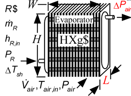
R$: name of the refrigerant
m_dot_R: refrigerant flow rate (kg/s, lbm/hr)
h_R_in: refrigerant inlet specific enthalpy (J/kg, kJ/kg, Btu/lbm)
P_R: refrigerant pressure (Pa, kPa, bar, MPa, psia, atm)
DELTAT_sh: number of degrees of superheat (C, K, F, R)
V_dot: volumetric flow rate of air (m^3/s, cfm)
T_air_in: air inlet temperature (C, K, F, R)
P_air: air pressure (Pa, kPa, bar, MPa, psia, atm)
HXg$: string identifier for a finned circular tube heat exchanger in the compact heat exchanger geometry
W: width of heat exchanger face parallel to tubes (m or ft)
H: height of heat exchanger face perpendicular to tubes (m or ft)
th_tb: tube thickness (m or ft); if set to a negative number then a reasonable value is assumed
N_circuits: number of parallel flow circuits for the refrigerant
Outputs:
L: length of heat exchanger in flow direction (m or ft)
A_R: required heat transfer area for the refrigerant (m^2, ft^2)
UA: overall heat transfer coefficient (W/K ,Btu/hr-R)
Q_dot: overall heat transfer rate (W, kW, Btu/hr)
h_R_out outlet specific enthalpy of the refrigerant (J/kg, kJ/kg, Btu/lbm)
T_air_out: outlet temperature of the air (C, K, F, R)
DELTAP_air pressure drop on air side
f_sh: fraction of the evaporator area that is in the superheat section
Example:
$Load Component Library
$unitSystem SI C kPa kJ mass
$TabStops 0.2 4.5 in
$Varinfo A_R units=m^2
$Varinfo DELTAP_air units=kPa
$Varinfo L units=m
$VarInfo h_cond_out units=kJ/kg
$VarInfo h_R_in units=kJ/kg
$VarInfo h_R_out units=kJ/kg
$VarInfo Q_dot units=kW
$VarInfo T_air_out units=C
$VarInfo T_R_sat units=C
$VarInfo UA units=W/K
R$='R134a' "refrigerant"
m_dot_R=0.008 [kg/s] "refrigerant mass flow rate"
T_cond_out=38 [C] "condenser exit temperature"
P_cond=1 [MPa]*convert(MPa,kPa) "condenser pressure"
h_cond_out=enthalpy(R$,T=T_cond_out,P=P_cond) "specific enthalpy of refrigerant exiting condenser"
P_R=175 [kPa] "evaporator pressure"
T_R_sat=t_sat(R$,P=P_R) "evaporator saturation temperature"
h_R_in=h_cond_out "specific enthalpy of refrigerant entering evaporator"
x_R_in=quality(R$,h=h_R_in,P=P_R) "inlet quality"
T_air_in=5 [C] "air inlet temperature"
P_air=101.3 [kPa] "air inlet pressure"
V_dot_air=0.08 [m^3/s] "volumetric flow rate of air"
HXg$='fc_tubes_s80-38T' "HX core geometry"
th_tb = 0.9 [mm]*convert(mm,m) "tube wall thickness"
W=0.2 [m] "length of tubes"
H=0.26 [m] "height of flow channel"
DELTAT_sh=5 [DELTAK]
N_circuits=1 "number of parallel circuits"
Call evaporator3_cl(R$, m_dot_R, h_R_in, P_R, DELTAT_sh, V_dot_air, T_air_in, P_air, HXg$, W, H, th_tb, N_circuits : L, A_R, UA, Q_dot, h_R_out, T_air_out, DELTAP_air, f_sh)
{Solution:
A_R=0.3446 [m^2]
DELTAP_air=0.0239 [kPa]
f_sh=0.05312
h_R_out=246.6 [kJ/kg]
L=0.1368 [m]
T_air_out=-6.101 [C]
UA=95.49 [W/K]
}