Using Check Boxes
A check box can be placed on the Diagram window using the Add Check Box button on the Diagram window toolbar (Professional license). A check box allows the equation set that EES solves to be modified by the check box setting. The function of the check box should be more clear with the following example.
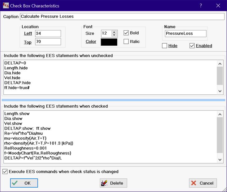
After selecting the Add Check Box button on the toolbar, the dialog window shown below will appear. The dialog allows the caption text, location on the Diagram window, and font to be specified. The location can be later changed by dragging the check box to the desired location while the Diagram window is in development mode. or by using the arrow keys.
The checkbox can be given a name. If a name is provided, the attributes shown with underlined text can be set with EES variables. For example, the left position of the check box in the example below could be specified by setting the value of PressureLoss.left. The specific variables that can be set in the Equations window for a check box are:
Name.left
Name.top
Name.hide
Name.fontcolor
Name.color {changes the background color}
Name.enabled {set to true# or false#}
where Name is the name provided for the checkbox. Note that Name can be specified to be an array variable, e.g., ChkBox[1]. In this case, the array subscript is moved to the end of the variable name to be consistent with the convention in EES concerning the location of the array index. If the name provided for this checkbox is ChkBox[1], the variables that can be set in the Equations window are:
ChkBox.left[1]
ChkBox.top[1]
ChkBox.hide[1]
ChkBox.FontColor[1]
ChkBox.Color[1]
ChkBox.enabled[1]
If a Check Box control is not enabled, its state cannot be changed in Application mode.
The values of the attributes can be copied to EES variables using the GetDiagramAttribute function.
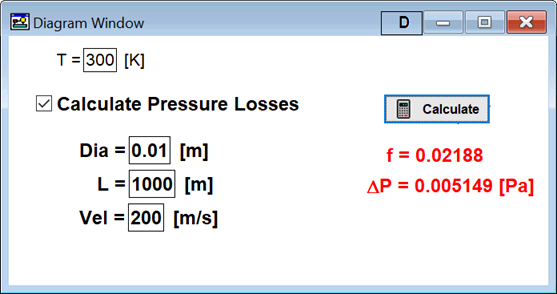
In the following example, several input and output text items have been defined and been given names. These text items are either hidden or shown depending on the check box setting by appending .hide or .show to the names. The check box dialog provides two windows in which EES commands (comment, equations and directives) can be entered, just as if they were entered in the Equations window. If the check box is unchecked, the commands in the first window are included with other commands in the Equations window when calculations are initiated. If the check box is checked, the commands in the second window are included.
If "Execute EES commands when check status is changed" is selected, EES will attempt to execute the commands in the unchecked or checked window, depending on the setting of the check box, directly after the change is made to the check box. This capability is most useful when the check box setting affects the display in the Diagram window in some way. In the example below, some text inputs and outputs are immediately hidden if the check box to calculate pressure losses is not selected. Graphical objects and buttons can be hidden or positioned in this manner as well. Note that the width and height of this dialog can be changed by dragging the triangular control at the bottom right of the dialog window. Also, the sizes of the edit controls used to hold the equations can be changed by dragging the sky blue splitter bar between the edit controls up or down.


All settings for a check box are made in the Check Box Characteristic dialog. This dialog can be made to appear while the Diagram window is in development mode. by double-clicking on the check box or by clicking on the check box to select it and then clicking the check box button on the Diagram window tool bar.
The status (checked or not checked) of a check box can be determined using the GetDiagramAttribute function. It can be used in the Equations window or in a macro
See also: Using Radio Button Groups