


Adding Text, Inputs, and Outputs in the Diagram Window
Use the Add Text button in the toolbar to add a text item to the Diagram window or to change the characteristics of the selected text item. A dialog window will appear with radio buttons for Text, Input variable, and Output variable. The Professional license also offers the option adding Formatted text.
Adding Text
Clicking the Text radio button will provide an edit box in which the text can be entered, as shown in the figure above on the left. The text will initially appear in a default position within the Diagram window (or child Diagram window) when the dialog is dismissed. It can then be dragged to a new position by pressing and holding the left mouse button down while sliding the text to the desired location. Alternatively, the text can be moved using the arrow keys, which allow fine control of position. Holding an arrow key down for three or more seconds will cause the speed of movement to increase. The text or any of its characteristics can later be changed while in development mode by double-clicking the left mouse button (or by clicking the right mouse button) while the cursor is positioned over the text.
There are 6 buttons (shown at the top of the leftmost figure above) that can be used to add special features to text. The X_y and X|y will cause the selected text in the Text edit box to be a subscript or superscript, respectively. The ¶ button will insert a line break. Using this button, it is possible to create a multiline text item. The position of the line break is shown with a \m in the Text edit box. The other three boxes will introduce a special character or modify the selected character with an overbar, dot or other options.
Clicking the Apply button will place the text item on the Diagram window and allow specifications to be entered for the next text item. In this way, many text items can be placed on the Diagram window in this one dialog session. When editing an existing text item, the Apply button is replaced with the Delete button. Clicking the Delete button will delete the selected text item. Selected text can also be deleted by pressing the Delete key
Adding Inputs
The Input variable option functions in a manner similar to adding text, except that the text that appears on the Diagram window is the value of an EES variable that is input by the user. The EES variable is selected from an alphabetical list of currently defined variables in the main program (i.e., the equations residing in the Equations window that follow Functions, Procedures, and Subprograms. If the variable you want to be an input has not yet been defined in the Equations window, select *** New Variable *** at the bottom of the list. If the Include Identifier check box is checked an edit box will appear below the check box where an identifier can be entered. The default identifier is the name of the variable. The identifier is displayed to the left of the input box separated by an = sign. The variable units may (optionally) be displayed with the variable value, as seen in the above center figure. An Input Variable will by default be displayed with the value enclosed in an editable rectangle or as a drop-down list for strings. The edit rectangle remains visible when editing is complete if the Frame Input option is selected. Input variables provide the same function as an equation in the Equations window that sets the variable to a value. When any of the command in the Calculate menu are issued, e.g., Solve or Min/Max, EES will first examine the Diagram window (if it is visible on the screen) to see which variables, if any, are set. Calculations can also be initiated directly from the Diagram window with a Calculate button. A value that is set in the open Diagram window cannot also be set in the Equations window.
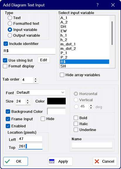
Two input options are available for entering information into string variables. A string variable is identified with a $ as the last character in its name and it contains string information, rather than a numerical value. When a string variable is selected for input, the Use string list check box appears providing a list of alternative choices for the string variable, as shown below. An Edit button will appear when Use string list is checked that will allow the existing choices to be entered, viewed and/or changed. The string choices are displayed in a drop-down list box that displays the available choices when the user clicks in the box. The drop-down list can be dragged to any location in the Diagram window while in development mode. An additional capability is that the strings in the drop-down list can be used to set the values of one or more EES variables. When using a drop-down list, it is often convenient to select *** New Variable *** from the Input Variable list box in order to create a new string variable that can be used to control the values of other EES variables. Note that the name of a string variable ends with a $ character.
By default, Input text items are enabled. If the Enabled check box control is set to unchecked, then the input cannot be changed in Application mode. Enabled can also be set programatically with a Professional license.

Adding Outputs
The Output variable option is shown in the rightmost figure at the top of this page. A variable that is to be displayed on the Diagram window is selected from the list of variables at the right of the dialog. After the calculations are completed, the newly-calculated values of the Output variables will be displayed on the Diagram window. If any change in the equations is made, the color of the output variables will be changed to gray to indicate that the calculated value shown may not be correct. If the Diagram window is foremost when the Solve command is issued, it will be updated with the calculated output values and remain foremost. The Solution window will not be displayed. However, it can be viewed by selecting Solution from the Windows menu. (The $ShowWindow directive can optionally be entered in the Equations window to allow any output window to be displayed after calculations are completed.)
It is possible to programmatically change a text specification in the Diagram window from an Output to an Input or vice versa using the capabilities provided in Drop-Down lists and Radio groups.
Enhancements Available in the Professional license
The Professional license provides the option to associate a hidden hyperlink with a Text item. Checking the Include Link control will provide an edit box where the link information can be entered, as shown at the top in the figure on the left. The link is usually a URL, but it can also be a .pdf or other type of file name. Clicking the text when the Diagram window is in Application mode will start the browser or program and display the page referred to by the link. Similar capability can be provided by a Link button.
The Professional license provides a small button to the right of the Hide array variables checkbox when entering Input or Output variables, Clicking this button brings up the Modify Variable Information dialog that allows the units, alternate units and display format of the selected numerical variable to be viewed or changed.
By default, the color of the value and units of output variables is set to gray before calculations are completed and changed to the designated color after calculations. The Show only After Calculations check box modifies this behavior so that the output variable is hidden until calculations are completed.
The Professional license provides an option to enter input values with slider controls. Click on the slider controls link for more information.
For input and output variables for which both units and alternate units have been specified, the Professional license provides the option to Show alt units and value in the units selection dropdown control. If this option is selected, the value of the variable is entered in the alternate units system and internally converted to the normal unit system for use in subsequent calculations. For an output variable, this option will result in the value of the variable being converted to the alternate unit system when it is displayed in the Diagram window.
The Professional license provides an option to enter the name of a file into a string variable using the standard open file dialog.
The Professional license provide an option to display text items at a specified angle between -90 and 90
The Professional license allows inputs to be entered as equations involving numerical values and/or existing EES variables. Click on Allow Equations for Input variables for more information.
The Professional license will provide a field to enter the name of the text item at the bottom right of the Add Diagram Text Item dialog. Assigning a name to a text item is useful only when the item is to have its attributes determined by the value of EES variables, such as for animation. If a name is provided, EES will create variables and associate them with this text object. For example, if the name of the text item is set to Refrigerant as shown in the figure above left for string variable R$, the following EES variables will be created (if they do not already exist) after pressing the OK button:
Refrigerant.left
Refrigerant.top
Refrigerant.color
Refrigerant.hide
Refrigerant.text$
Refrigerant.enabled
The text can be specified dynamically with the EES string variable Refrigerant.Text$. The names of the text attributes that are can be specified with EES variable names are underlined in the dialog when a name is provided. The created variables can optionally be assigned values in the EES program. For example, the position of the Refrigerant text item can be specified by placing the following equations in the Equations window.
Refrigerant.left = 100 {horizontal position is 100 pixels from the left of window; screen resolution is 96 or 120 pixels per inch}
Refrigerant.top = 50 {vertical position is 50 pixels from the top of the window}
Refrigerant.show {ensure that it is visible}
Note that if an array variable is used for the name, e.g., Text[1], EES will move the array index to the end of the variable name thereby creating variables
Text.left[1]
Text.top[1]
Text.color[1]
Text.Hide[1]
Text.Text$[1]
Text.enabled[1]
To hide or show a text item named Text[1], you could enter Text.Hide[1]=True# or Text.Hide[1]=False#. A simpler alternative that is accepted is to enter Text[1].Hide or Text[1].Show. Similarly, an input text item can be disabled by entering Text.enabled[1]=false#.
The height and width of the Diagram window are provided by the DiagramHeight# and DiagramWidth# functions. The position of a text item can be converted to inches using the PixelsperInch# function. The text can be hidden in Application mode by setting EES variable Name.Hide to a non-zero value where Name is the Name associated with the text item. Alternatively and more simply, just enter Name.hide or Name.show wherever an EES equation is accepted (e.g., Equations window, Diagram check boxes, etc.) or to hide or show the text item in the Diagram window.
The values of the attributes can be copied to EES variables using the GetDiagramAttributes function.
The Parametric Table could also be used to specify values of text attributes. If the variable associated with an attribute is not used in the EES program, the attribute value is taken to be the value specified in the dialog. If a value is specified with an EES variable, the EES variable value will override the value in the dialog when the Diagram window is in Application mode. The value specified in the dialog will be used in Development mode.
To unassociate the EES variable with an text attribute, clear the name field in the dialog and press OK.